
DIY WiFi Universal Sliding Glass Door Lock
May 19, 2021Today on the hookup we’re going to automate a sliding glass door lock for about $50. No more waking up in the morning and realizing that the door was unlocked all night, or laying in bed wondering if I remembered to lock it.
Time for me to show my cultural ignorance, do you guys even have sliding glass doors in other countries? In the US, or at least in Florida I’d say 90% of houses have at least 1 sliding glass door, and automated locks for them basically don’t exist, probably for good reason. Unlike the standard deadbolt on your front door which is mostly the same at least within your country, there doesn’t seem to be any standard for how these locks work, so what we’re going to do is totally abandon the normal lock, and make our own secondary lock, and then once we have that working well we can just disable the primary lock, or keep it as a backup.
Like a lot of my projects, this started out pretty simple, and then got gradually more complex as I made it work exactly how I wanted it to. At the most basic level, you can just buy one of these electric drop bolts, a smart plug, and a 12V adapter and you’ve got yourself a solution. Whenever power is applied the bolt extends and you can just screw the receiver into your door, or even just use double sided tape, which is significantly stronger than it needs to be considering the whole door is made of glass and if you really wanted to get in, there’s one clear and easy way to do it.
But for me, this solution had some issues: First, I wanted a manual button for locking and unlocking, second, I didn’t like the look of the two metal housings, and third the drop bolt only extends with the power on, so if we lose power the door just unlocks. So on that note, lets talk about the two types of electric locks. Any listing for an electric lock should say either “fail safe” or “fail secure”, fail safe means that on power loss the lock will be unlocked, and fail secure means that the lock will be locked without power. On amazon I could only find the “fail safe” version of this lock, which for me isn’t ideal, but thankfully its pretty easy to modify the fail safe version into the fail secure version.
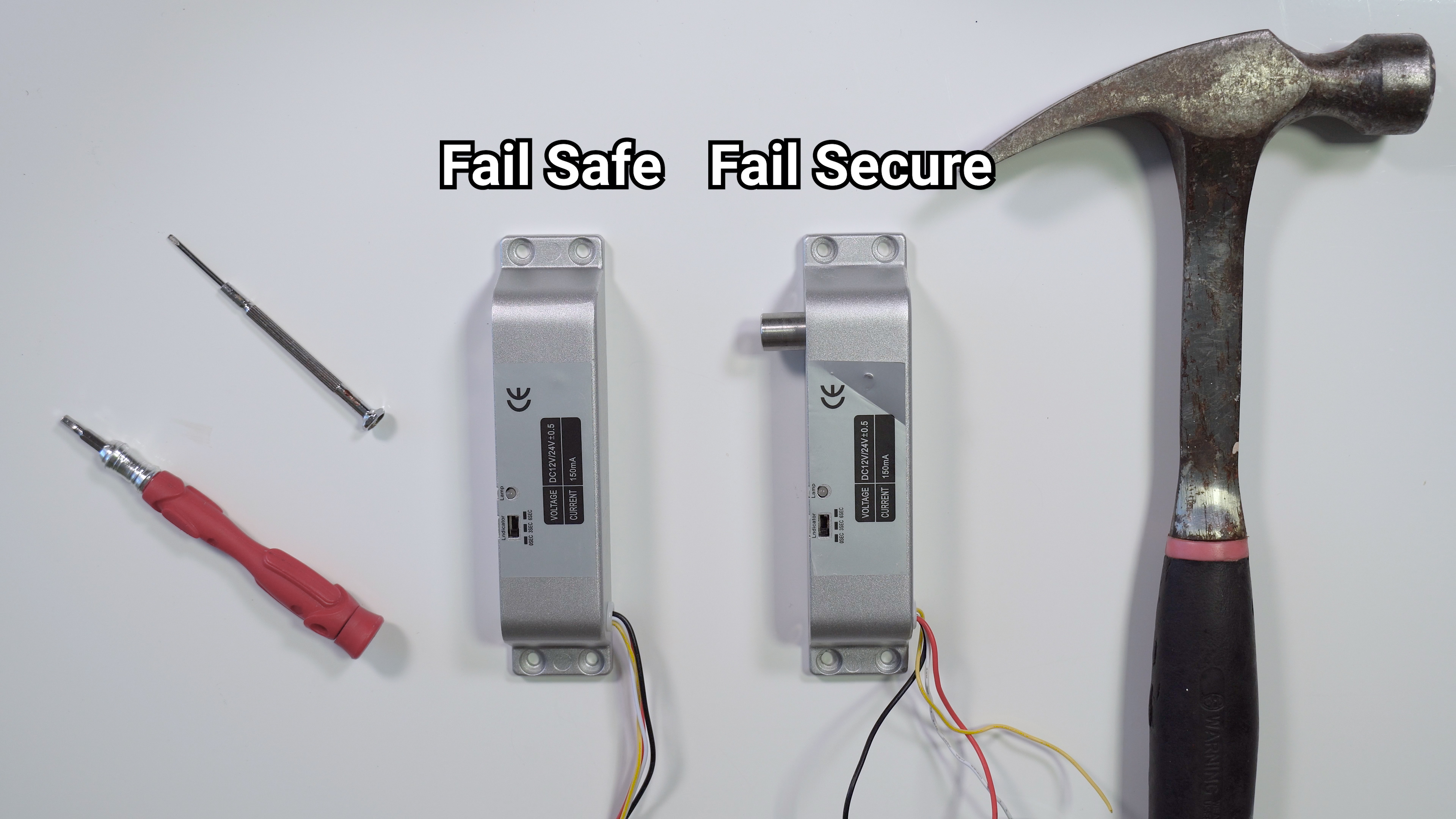
BUT! Stop! There’s probably a reason only the fail safe models are available. If your power goes out, like maybe during a fire, your door will lock and there will be no way to open it, leaving you trapped inside. That situation alone should terrify you enough to stop you from doing anything stupid, but if you need another reason not to do it, unless you have an alternate means of opening the door, it’s also against fire code basically everywhere in the world. In my situation, fail safe isn’t necessary because I can just open the other side of the door, but if you don’t have an alternate method for opening your door you should absolutely opt for the fail safe model. Please don’t do something stupid and put yourself or your family at risk.
Having said that, to convert from fail safe to fail secure, you’ll need to disassemble the lock and then use a hammer and a small punch of some kind to remove the hinge pin for the actuating arm. Once that hinge pin is removed, just rotate the mechanism 180 degrees to switch from normally open, to normally closed. The other thing that needs to be modified here is we need to disable the reed switch on the circuit board. This switch is there to only allow the door to lock when it is in the correct position, however, in our case this means that it can only UNLOCK when its in the correct position, meaning if the drop bolt ever gets extended when it isn’t in the correct position, there’s no way to retract it and therefore no way to close the door. Anyways, all you have to do is get some wire and wrap it around each side of this reed switch.
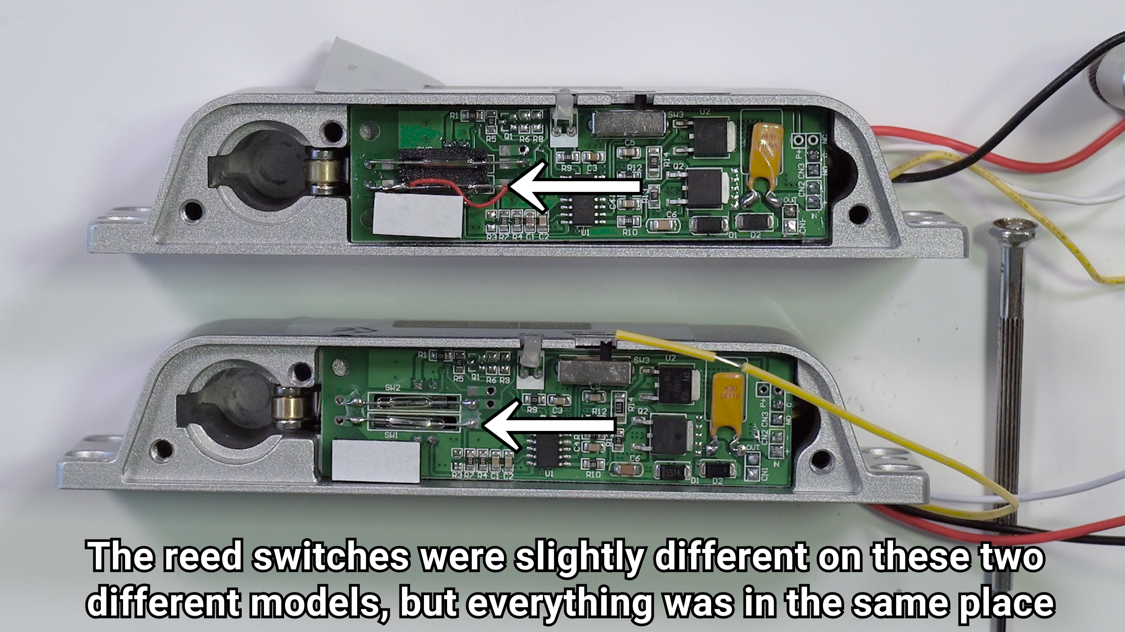
I also through a small bead of solder on it for good measure, but it’s not totally necessary. You can leave the other reed switch alone, which just gives you feedback on the position of the door through the white and yellow wires. If you don’t need positional feedback you don’t need to hook up those wires at all.
Next, we need a wifi smart relay, with a switch input, that can run off of 12V. Sounds like a job for a Shelly1 to me. To wire it up you’ll first switch the jumper on the shelly1 from regulated mode to 12V mode, but be careful because if you screw this up by reversing your positive and negative wires or providing more than 12V that will be the end of your shelly. Attach a short red wire to the + terminal, and another to the I or input terminal, then a black wire to the – terminal. The red wire from the lock will connect to the O terminal on the shelly, which is the output.
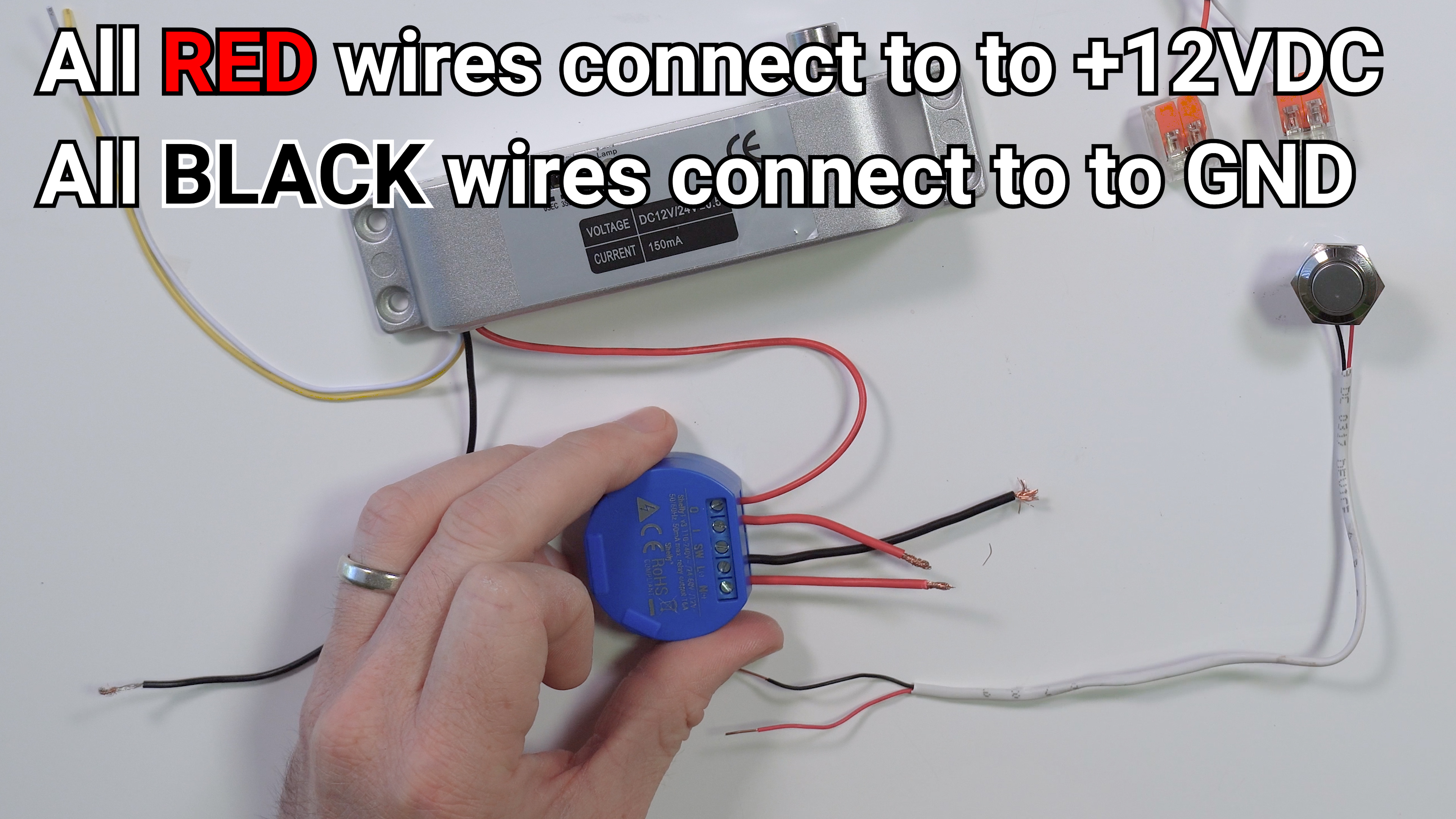
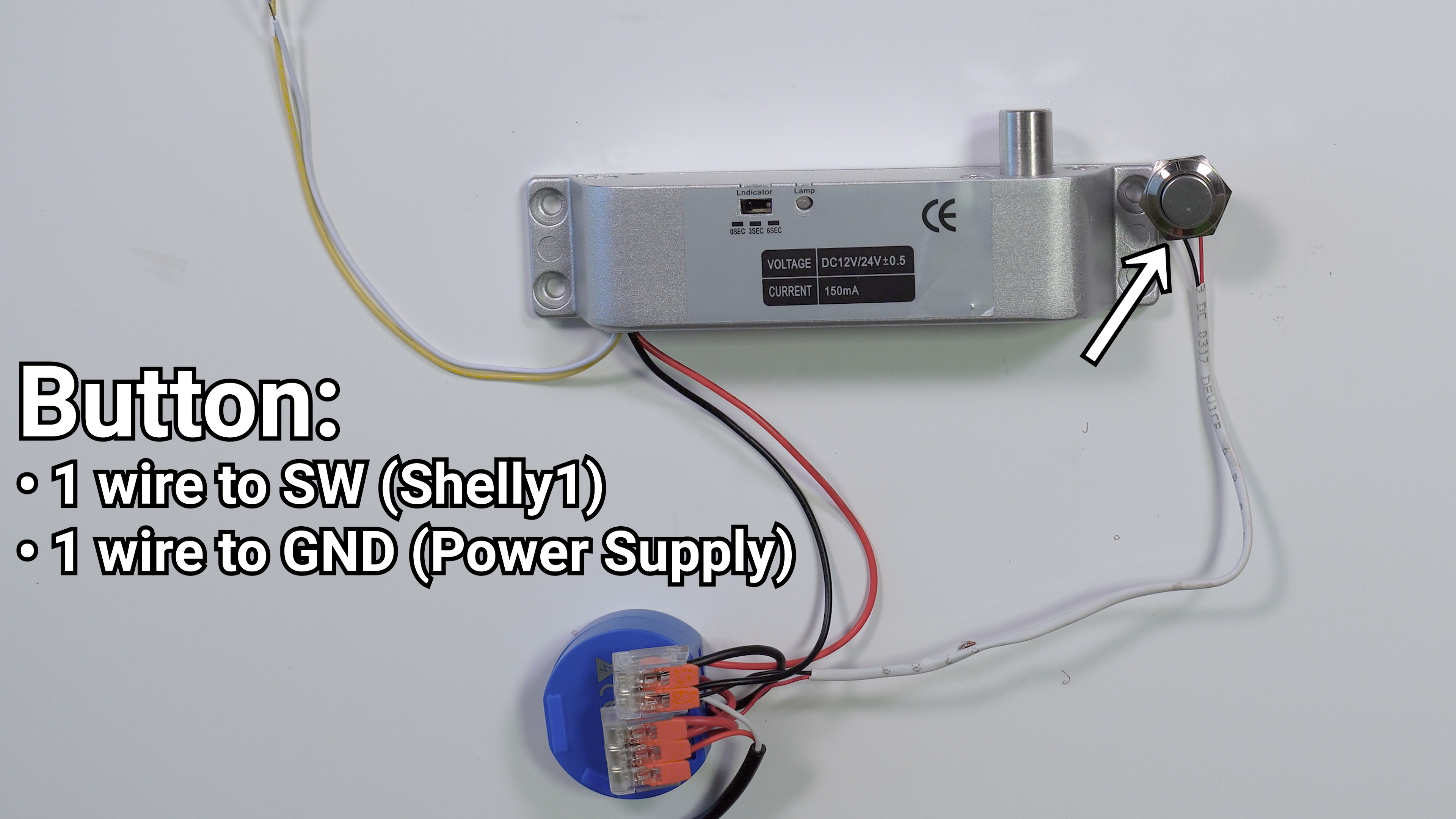
All the red wires will connect to the positive wire on your 12V power supply and all the black wires, including the black wire from the lock will connect to the negative wire on the power supply. Additionally, if you are going to hook up an external button one wire of the button will hook up to the negative wire on the 12 volt supply and the other will hook up to the SW terminal on the shelly. If you don’t want a button you could also hook up the white wire from the lock to the SW pin and the yellow wire to the negative on the power supply, which would give you positional feedback in the shelly app to let you know when the door is open or closed using that other reed switch in the lock.
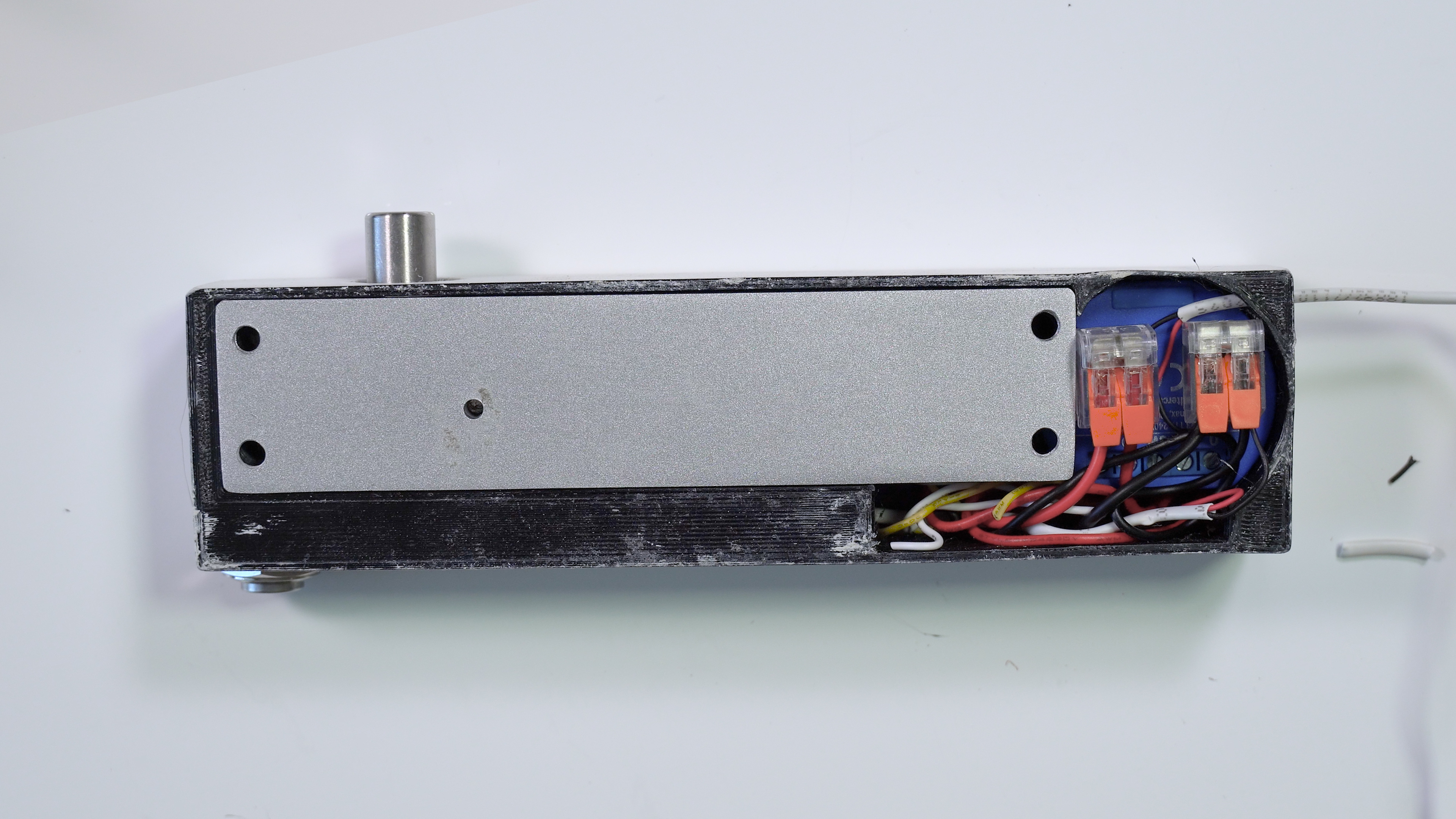
I also decided to 3d print a case, so I’m going to take this whole mess and put it inside this nice little package. There’s a spot to run wires for the button and the mounting holes line up with the mounting holes on the actual lock. The parts just slide into place and are friction fit. I also left enough room above the shelly1 to fit two lever lock style connectors for easier wiring.
In addition to the case, I also printed a custom size shim for above the lock so it would line up properly with my door frame and a custom receiver for the drop bolt pin. I actually made all these models in tinkercad, which is a really simple, free online modeling tool. I’ve got all the projects linked if you need to modify them for your use case. For instance, if you need a larger or smaller shim, all you have to do is open up that tinker cad file, click on the object and input the height that you need in millimeters. Then hit the export button, choose STL and you’re ready to print.
I attached my main lock into the frame of my door with some 3” screws, and my custom receiver with some gorilla double sided tape. If that’s not strong enough for you, you can screw it into the door, but be careful not to screw into your glass pane while doing it. I routed my power wire down the edge of the door to a nearby outlet behind my curtain and then removed the standard lock, because it has always been a point of confusion when we have guests and they constantly flip the different levers and switches unsuccessfully trying to open the door.
Once you’ve got the hardware installed you can control it straight from the shelly app, or integrate it into a home automation hub like home assistant for more automated control. For instance, I’ll have the door lock whenever the house goes into “away mode”, meaning neither mine nor my wife’s phone are within the GPS zone of our house. I’ll also automatically lock the door at night when the bedtime routine is triggered, and I’ll unlock it in the morning, and as the house goes from away mode to occupied. If I ever want the door to be locked while I’m home I can just press the manual button or activate it in home assistant and it won’t change again until the next automated state change.
Overall this is my favorite type of project, just enough tinkering to be fun without being overwhelming, relatively cheap, and solves a problem that I had without introducing different issues. The only downside of this project is power usage since the drop bolt is an electromagnet. The shelly by itself uses about 2 watts of power, and when the lock is engaged that jumps up to 6 watts. That means that if I estimate 12 hours of unlocked time per day that would be 35 killowatt hours per year, or just over $2 a year in electricity costs at 6 cents per kilowatt hour. This is easily worth it for me, but if your power costs are significantly higher it may not be for you.
Amazon and AliExpress links for everything that you need to complete this project are down in the description, along with my tinkercad projects and STL files. If you’ve got questions about the project or you get hung up during the processes just leave a comment here or better yet come get help from the thousands of automaters on the hookup home automation facebook group.
Thank you so much to all of my patrons over at patreon for your continued support of my channel, if you’re interested in supporting my channel please check out the links in the description. If you enjoyed this video please hit that thumbs up button and consider subscribing, and as always, thanks for watching the hookup.
🔥Parts Links🔥
-
Electric Drop Bolt
(AmazonUS): https://amzn.to/3fojISM
(AmazonUK): https://amzn.to/3v0ad2L
(AliExpress): https://s.click.aliexpress.com/e/_AY4oxB
-
Shelly1
(AmazonUS): https://amzn.to/3h10OR7
(AmazonUK): https://amzn.to/3tXc9YD
(Shelly Direct): https://shop.shelly.cloud/shelly-1-wifi-smart-home-automation?tracking=560nL2gjFHG8j8IgeYDCEJFFBmASWMAYl4YeFi6LHroq2RZDMT#50
-
12V Adapter
(AmazonUS): https://amzn.to/3eU8Dda
(AliExpress): https://s.click.aliexpress.com/e/_AgSOZL
-
Buttons